Assembling XYZ stage for Bath Interferometer
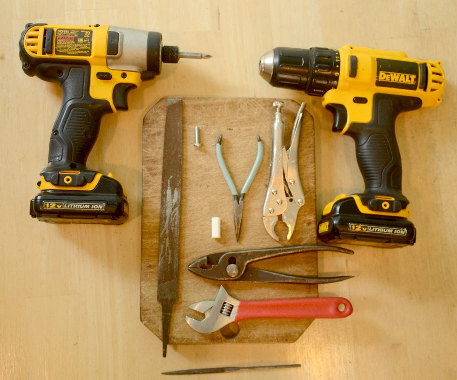
Tools you will need (you shouldn't need the tiny file at the
bottom). These are the tools we use. Some are
optional. The white
piece, called "the helper tool", should be included in your
parts. The #8-32 screw for tapping stage and knobs is also
included.

All
steps below were performed by one person! It's easier with a
third hand but we did it with only two hands. All photos and
descriptions are written for if there is only one person assembling the
stage.
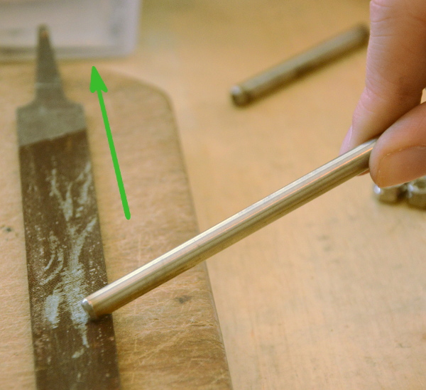
First clean up the 6 aluminum rods. Rub the ends of the rods against a file as shown in picture to
clean it up. It should only take maybe 10-20 seconds per end of the aluminum rod if you are forceful. Move in the direction that the file is working harder (moving rod towards handle of file). Use a flat angle like in the photo as we only care about removing sharp burrs.
The threaded rods shouldn't need any modification. The ends have been tested already (by us) by threading a nut.
You could try this yourself to be sure.
If
one end is fine and the other not so good then put a nut on the good
end and run the nut all the way to the bad end and then off the end to
repair the threads.
Lower Assembly (z stage)

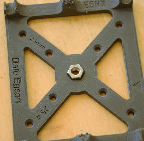
Place tripod nut
(1/4-20 thread) firmly into hex hole of z stage as shown. Push
firmly. If it seems loose then glue it in place but it usually
doesn't need any glue. It is possible to do this step after
everything else is assembled (including gluing) so don't panic if you
missed this step. It is more difficult however.
Z MOVEMENT ASSEMBLY
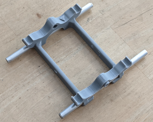
Locate the largest 2 plastic parts (z stage and z slider)
Using the 2
longest aluminum rods insert them into the
lower portion of z slider part like shown.
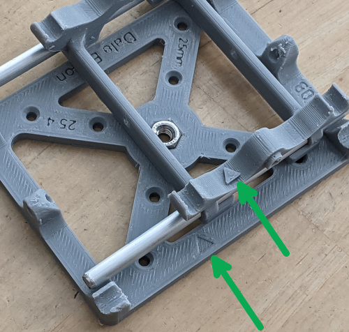
Note the
location of the triangles on the 2 plastic parts - they line up (not
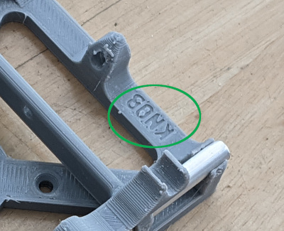
exactly - but same side of the part). If you get this wrong then
the "KNOB" wording on the bottom part will indicate the wrong side when
you are at the step to do the knob. It's also good to line up the
triangles because we make sure the parts fit perfectly but we only test in this
orientation.
Snap/push metal rods straight down into z stage as shown.
Note that we
already filed parts as needed to get it to fit perfectly (within less
than 0.1mm) before we shipped them to you. Make sure the the z slider moves with
just gravity as shown in video below.
If it takes just
a tiny tiny bit of force (say a little shaking) then it's good
enough but having no friction makes the XYZ stage a joy to use as it is
important to eliminate all play/backlash. Also consider washing
the rods in soap and water if they look grungy or try blowing dust
off the parts.
If you still want to lower the friction - click here for more details
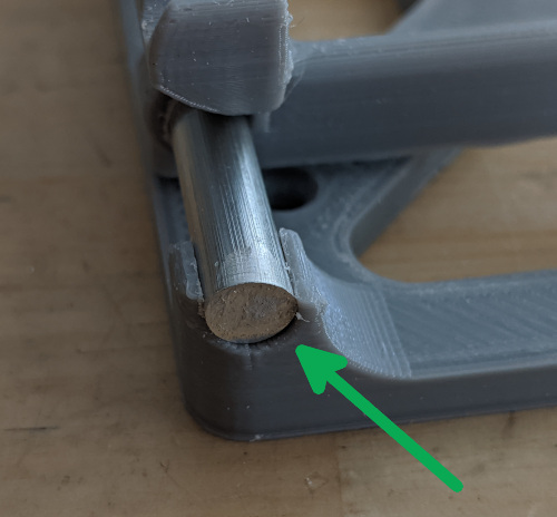
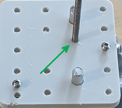
Too loose?
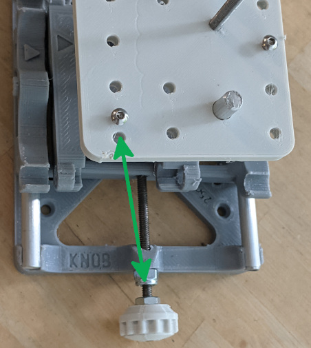
If either or both rods slide too easily through the plastic you can add
a drop of glue where the green arrow is on the photo above. I
recommend waiting until everything is assembled before gluing.
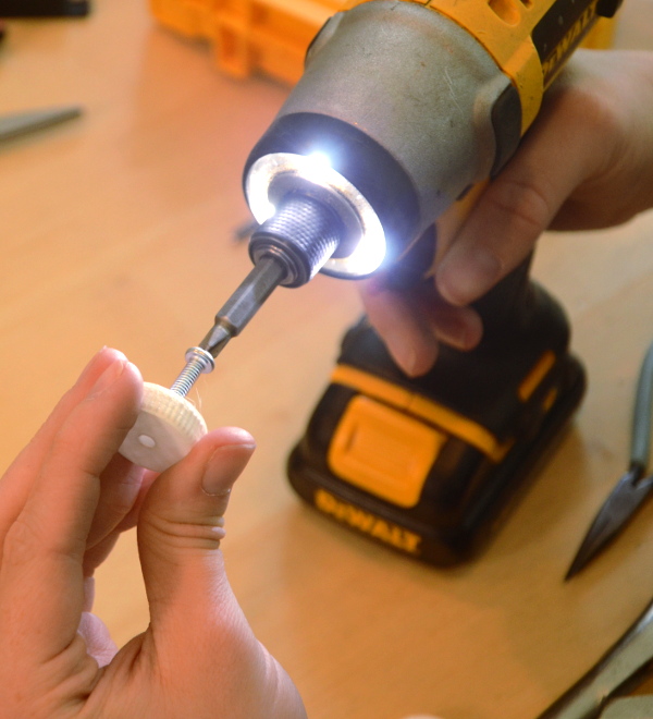
Pre-thread the 6 lock nuts. Use one of the screws as a tap and pass it in and out of each lock nut at low speed twice.
Twice is plenty. More than twice will defeat the locking
function. Also more than twice and the nylon in the lock nut can
melt
and cause problems. After each lock nut threading let the screw
cool before doing the next. Melting the 3d printed plastic parts
using threading is a good thing and lowers friction. Melting the
nylon in the lock nuts is a bad thing and increases friction.
Tap the helper
tool using a supplied screw as shown. Move the screw in and out 2
times. The screw gets hot fast and can melt the plastic, so take it out
immediately. Let the screw cool down for maybe 30 seconds after each
time you use it to tap threads.
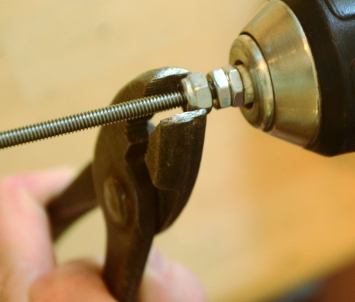
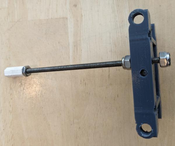
Assemble helper
tool with one or two nuts as shown below. Use wrenches to make
things quite tight without stripping the plastic helper tool.
Because the drill grips the plastic - this tool will allow you to do
much more clockwise torque than counter clockwise. So when
"fighting" a lock nut you will only be able to go clockwise on the
drill.

BE VERY CAREFUL NOT TO LET THE SLIDER HIT THE BASE - if things tighten completely something will strip and most likely it will be the z slider.
Getting a new
part from me is just $2 plus $3 shipping (in usa). I had one customer
who simply bought the next larger size thread from a hardware store and
drilled out the holes larger in everything related to that one axis.
That works fine as well.
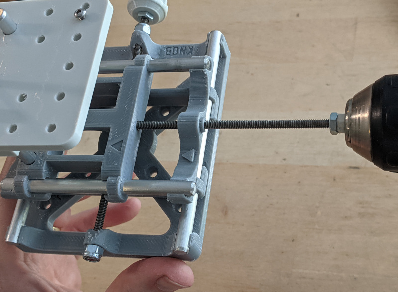
Make sure drill is on clockwise and insert longer rod into the side away from where bottom piece says "KNOB" as we will
try to add the knob lock nut first. after this step.
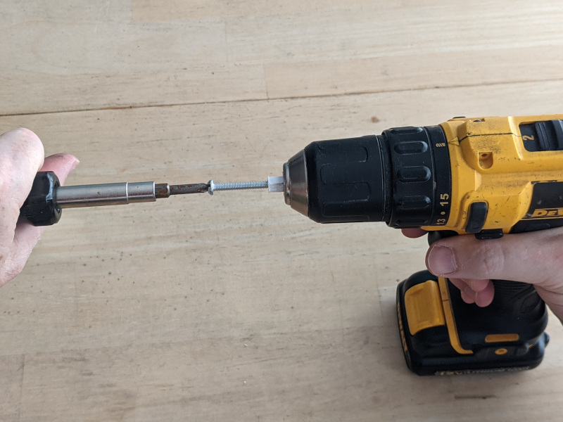
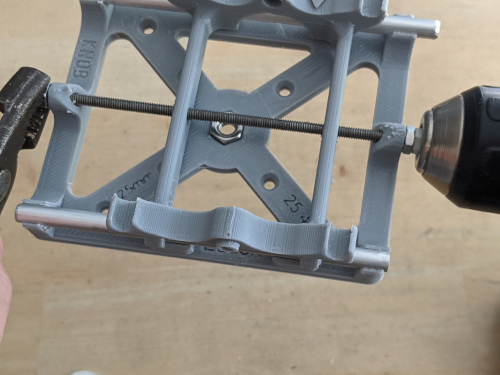
Using electric
drill run it all the way through. While keeping the moving stage
somewhat centered, go back and forth (about the length of one threaded
section or about 1/4 inch for this part) about 40 times at high speed (around 40
times for my kit, or about 10 times if you printed it yourself with PLA which melts at a
lower temp), to melt and
form a nice perfect tap/threading. Check the rotational friction by
spinning the assembly. It should be very little friction.
BE VERY CAREFUL NOT TO LET THE SLIDER HIT THE BASE - power tools can wreck things fast.
Put a lock nut
on the far end. Tighten it by hand until it gets to the
nylon. Use some type of wrench and the drill to get the nut as
far on as you can get. The drill should be on lower speed whenever fighting a lock nut as high speed can overheat the nylon and melt it into the threads.

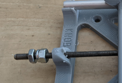
Remove helper tool (and nut).
Again
note that it says "KNOB" on the base at one end of the threaded rod -
clearly visible in above photo. If you got the wrong end don't
panic - just move to the next step.
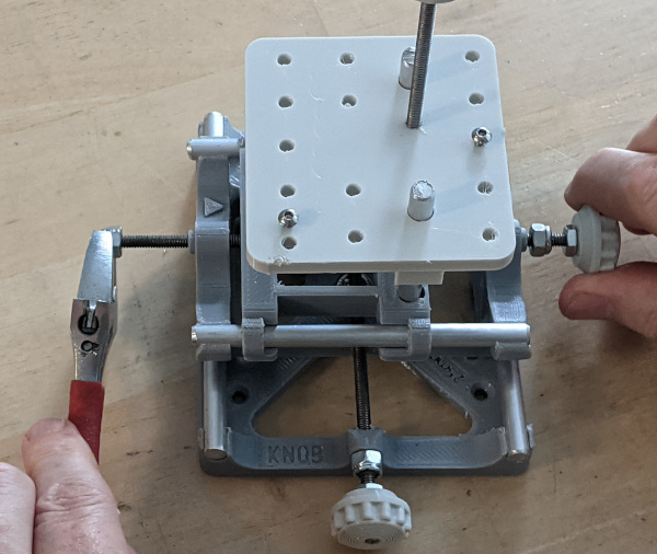
Add
a second lock nut to the other end of the threaded rod such that there is a lock nut on each end (shown below). Use two
wrenches to tighten both knobs. Be very careful not to crush the
plastic base. Check frequently how much play there is by sliding
the threaded rod back and forth.
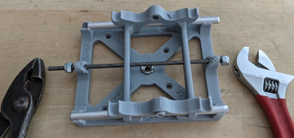
On the end away from "KNOB" you want the nut tightened until the
threaded rod sticks all the way through but just barely: flush with the
end.
Don't tighten
these lock nuts completely just yet - just get far enough so there is
plenty of room for adding the knob. Once the plastic knob is
attached it's much easier to precisely position the lock nuts.
I got lucky as
you can see above and could skip a step and add the knob now as there
is room on the left side for the knob. However, we'll assume
there's not enough room yet.
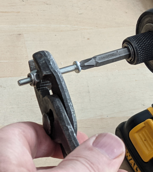
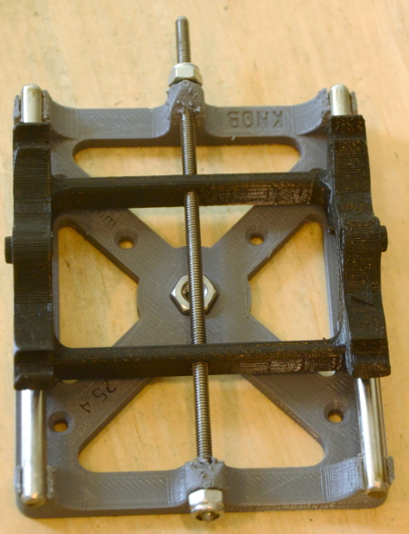
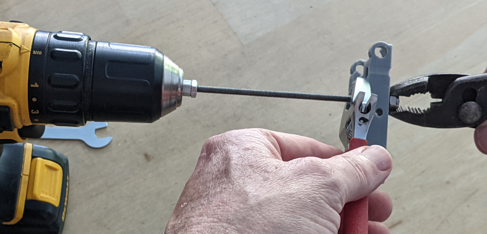
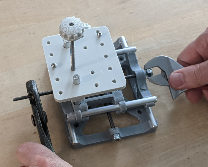
If you are
alone, it's helpful to use a vice grip unattended on one lock nut (blue
arrow) and then try to grip the thread with your fingers with one hand
and use a wrench to turn the other lock nut. If you have a "third
hand" (second person) then that person can hold the blue arrowed lock
nut with any kind of wrench. If your fingers aren't strong enough
you can try needle nose pliers (green arrow). We did this very
close to the end of the thread so if the threads are damaged a little
in this particular spot it will cause minimal problems.

Tighten until it looks like this (again it can be a little loose - you need room for the knob on the KNOB end):
Before adding
the knob - it's easier to pre tap the knob. Tap all the knobs.
Add a nut and then a knob.
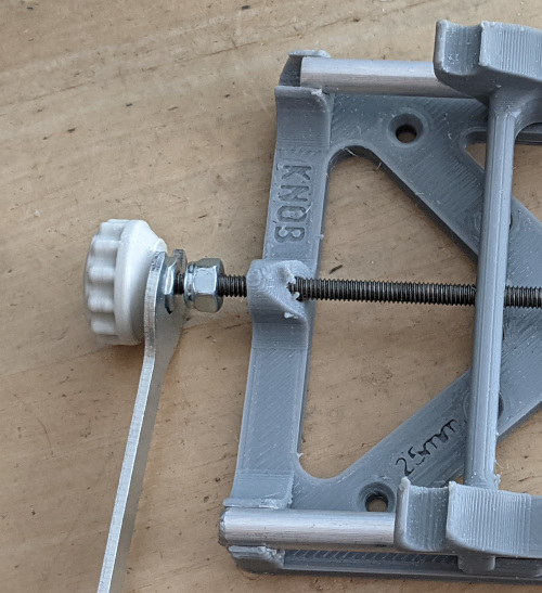
Ideally screw knob on until threaded rod is just flush (almost sticking
out of the knob). We didn't have room so we went as far as we
could and tightened the nut to the knob before adjusting lock
nut.
special trick with plastic knobs!
Once the nut and knob are tight
together you can use them to tighten the lock nut. Once you have
a knob on it's great as you can apply enough torque to defeat the lock
nut. If you want to go clockwise, just turn the knob with your
fingers. Counter clockwise use the nut and thin wrench as shown
above and below.
Another way to think of this - when fighting lock nuts - if you want to
turn the plastic knob clockwise - just go for it - if you want to turn
the plastic knob counter clockwise - put a wrench on the nut that is
touching the knob instead.

Screw on knob until the threaded rod is just flush (almost sticking out
of the knob). Of course loosen the thin nut first and retighten after.

Using
the "special trick" above in blue text, adjust both lock nuts so they
are up against the base such that there is no play, but also so that
there is no increase in resistance when you turn the knob.
lower assembly should be complete
Upper Assembly (Y axis)

Tap the top
platform hole with one of the supplied screws
(just like you did
with the knobs). The hole shown below with green arrow. See
picture below that as well. After it is through, if it is
crooked,
you can run it back and forth many times which will get hot and melt
the plastic and as you run it in and out push in a radial direction to
slowly move the screw perpendicular to the stage surface. We only
have to tap this hole because we will be spinning the stage on by hand
without power tools and it's hard to get the stage tapped without power
tools. You want to make sure the screw turns with very little
friction. Although this can be fixed later - it's easier to do
now. So you might want to run the screw back and forth quite a
few times to melt the hole so friction is low. About 10-20 times.
You want the friction on the screw so low that you can't feel
any friction.

Sometimes, even
when the threads seem perfect at this point, the friction seems too
high after things are further along in assembly. If this happens,
remove the stage (white part in picture just above) and tap with the
3rd threaded rod using a fast electric drill and the helper tool. The
threaded rods have a very slightly larger diameter than the phillips
head screws.
Find the
shortest threaded rod - that will be our vertical control. Put it
in the drill with a nut (or 2) and the helper tool and run another lock
nut all the way down the rod (on slow speed).

slow speed!
Then remove the helper tool (and nut(s)) and switch it to the other side. Add
the xslider (the smallest stage part as shown in photo) and get the
last lock nut started by hand.
While drill is attached to the helper tool use the drill and a wrench on the
lock nut to tighten the latest lock nut until the thread is just barely
sticking out (as shown below).
Then tighten the
other lock nut to just almost squeeze the x slider. We used the
drill to just hold things from spinning but also the black wrench to
make sure that the desired lock nut turned and nothing else. The
drill is our "third hand" in this example. You need a "two
against one" (drill plus one lock nut versus the other lock nut) to be
sure that the correct lock nut tightens.
Get the tension perfect -
you want zero play if you try to slide the threaded rod through the x
slider. But you want it loose enough so that there is no extra
friction needed to rotate the threaded rod. It's easiest to get
the tension perfect now as you won't be applying torque to these two
lock nuts going forward so they will stay where they are throughout the
remaining assembly steps. Actually you can get the tension
perfect after you get the stage and knob assembled if you want.
Just don't forget to eventually get the tension perfect so that there is no play
but not so tight that there is added friction.
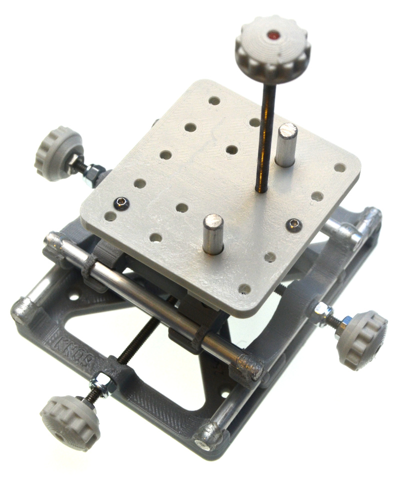
Remove helper tool and nut. Add the two shortest rods and then add the top
stage so they are flush with the bottom of the x slider. If you didn't tap the hole on the stage then tap it
now.
Make sure friction is very low in the top stage.
If not run a tap screw back and forth through the hole in the stage
until friction is low. Try moving the stage by spinning it on the
rod where you only grip the threaded rod (at one or both ends) and
shake the rod to spin the stage and lower it until it hits the two rods. If you can't spin it like this then
friction is higher than recommended and try re-tapping the hole through
the stage.

Add a nut and
knob to the top of the threaded rod and lower the stage through the two rods and now the upper stage is done.
Did you remember to get the tension perfect where the 2 lock nuts
squeeze the X stage? They should be tight enough that X stage
won't move back and forth but loose enough that there is no extra
tension. Check this now before moving to the next major step.
Use the "special trick" (blue text far above) to adjust these lock nuts
if needed.
Congratulations
- you are 2/3 done.
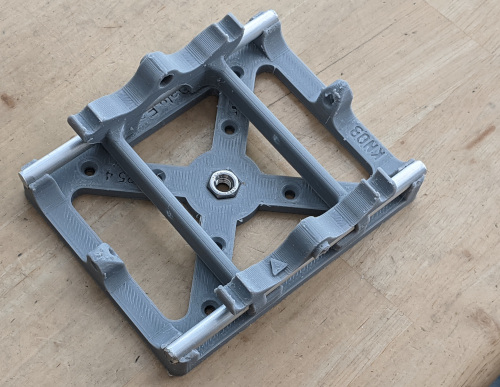
Combine Lower and Upper stage
Note triangles
. We test fitted your plastic parts with the triangles together although it should still slide frictionless the other way.

More importantly
than aligning triangles is that the small M3 screw in the corner of the
top of the stage should be lined up such that the Z screw on the lower
assembly is closest to it.
That little M3 screw is the one
that will hold the interferometer. The Z screw knob will be on the
side away from your mirror under test and towards your camera

Add final aluminum rods as shown above (medium
length rods). Insert into upper assembly first and then push/snap the
rods straight down into the lower assembly. Push them in well and make
sure things slide well just like earlier. If things are centered
and you tilt the stage it should slide with gravity. If not then
maybe you need to clean up the plastic slightly (steps to do this are at
the very begining of these instructions. Also check that metal
parts are fully seated. If friction is still a bit
high, click here for more details and follow those directions to improve.
Too loose? If
either or both rods slide too easily through the plastic you can add a
drop of glue. I recommend
waiting until everything is assembled for gluing.
Get another long threaded rod (the final threaded rod).
Put helper tool
and nut (or 2) on the end. Run the threaded rod through.
As you put this long threaded rod through the X stage you may notice that one of the two holes is large and won't be threaded.
This is on purpose. We drill one side out wider than the threaded
rod and only one side of the x stage will be threaded. We found
that if we didn't do this then this axis would be tighter than ideal.
DANGER - DON'T LET THE XSLIDER GET TO THE DRILL END OR YOU WILL DESTROY/STRIP THE XSLIDER
Run it
back and forth until smooth. Keep the moving stage somewhat
centered. Typically 5-10 times for lower temp plastic (PLA) and
10 or 30 times for higher temp plastics. You can run the drill a
little longer (in distance) as the plastic area touching the threaded
rod is also longer. About 1/2 inch.
DANGER - DON'T LET THE XSLIDER GET TO THE DRILL END OR YOU WILL DESTROY/STRIP THE XSLIDER
Getting a new
part from me is just $2 plus $3 shipping (in usa). I had one
customer who simply bought the next larger size thread from a hardware
store and drilled out the holes larger in everything related to that
one axis. That works fine as well.
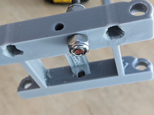
Next add
lock nut to side far from drill but first center the x slider!
Notice red arrowed gap in picture shows disaster about to occur if I go
much longer with the drill.
Just run the lock nut until you have about 1/4 to 1/2 inch of thread sticking out.

You don't need
to get it perfectly symmetrical just yet. In fact you only need to go a
little ways as we are about to tighten both lock nuts at the same
time. Also it's easier to adjust once you get one or two plastic knobs on.
Remove helper tool (and nut).
Put lock nut on
other side. Tighten lock nuts towards each other until at least
one is in the perfect position or a little past (it's easy to back up
the lock nut that is on the side with the knob after the knob is
attached).
Add nut and
knob to whichever side has more room. Nut should be very tight against knob - full finger tight
typically. Threaded rod should be flush with end of knob.
In the picture above you can see we need to tighten the left lock nut
which is easy as we can use the knob on the right (now that the
plastic knob is installed).
If we need to loosen the right lock nut we can also use the knob on the
right. If we want to loosen the left lock nut it's best to add
the second knob first and use that.
Again - the plastic knobs should be able to out-torque the lock nuts but only if you rotate the plastic knobs clockwise.
Add the second knob (if you have a 4 knob kit). Now you can
tighten the lock nuts so both sides have the same amount of threaded
rod sticking out. After that tighten lock nuts to the perfect
tension such that there is no
play/backlash (you can't slide the threaded rod back and forth) and
also it's not too tight (there is no added friction when you twist the
plastic knobs).
Final Step - gluing
It's time to glue any rods that are loose and keep sliding (if any).
I like to scratch the rod with a file a bit for a place for the glue to hold on as
shown below. I don't know if this is necessary. I rotate
the rod while scratching and again while glueing to get the glue under
the rod.
I like to use 5 minute epoxy although extra thick (gel) cyanoacrylate
or hot glue gun should work. A glue gun should work fine but
note that some of these plastics melt at a similar temperature to the
hot glue so go easy. Keep the hot
nozzle from direct contact with any plastic.
Don't let any glue fall to a lower rod and mess up the nice gliding action.
