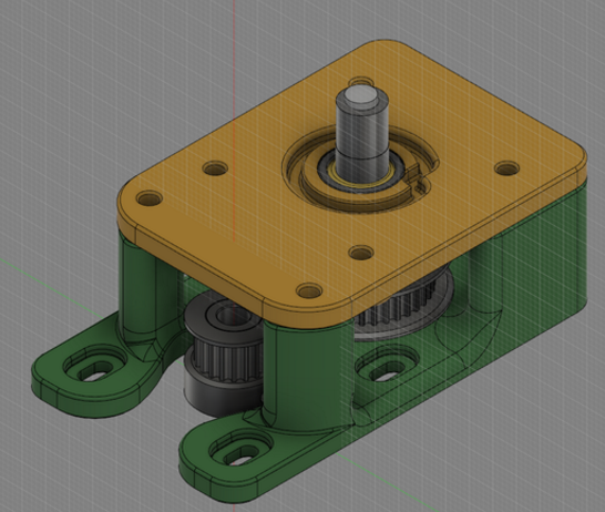
The original design is on Youmagine (search for meduza feeder upgrade) however I strongly recommend you print my modified base piece. All the parts are here on youmagine: https://www.youmagine.com/designs/meduza-um2-belt-geared-feeder-improved
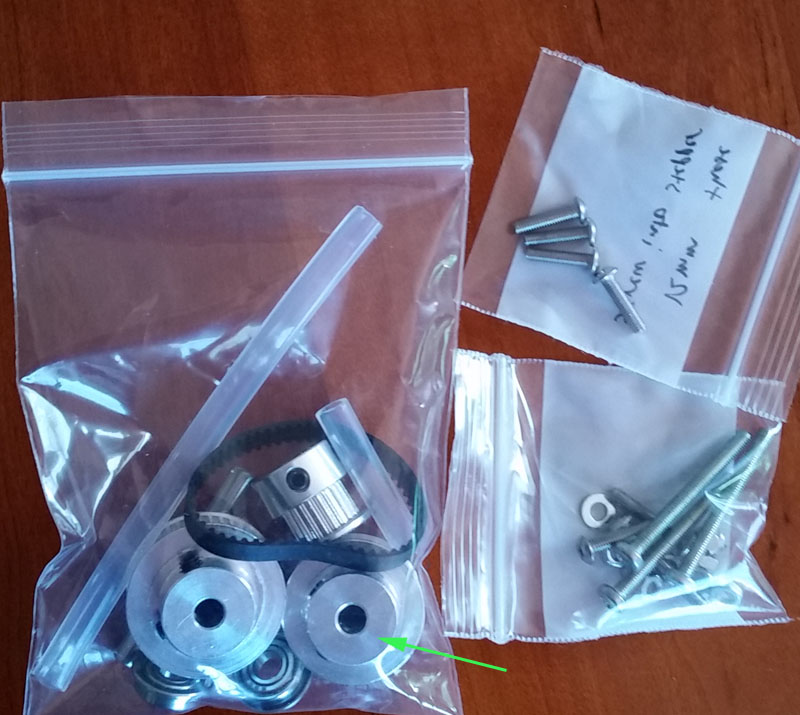
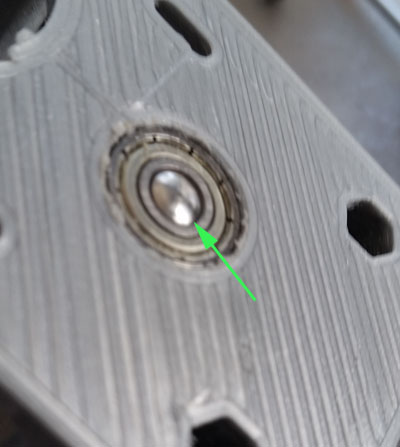
The parts that come in my kit from gr5.org/store - note that the green arrowed part is a 36 tooth pulley if you want 1.8X ratio. Not normally included and not recommended. Contact the store if you want a 36T at cost. The kit is currently $25.
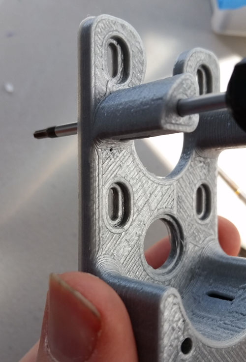
After printing the meduza feeder parts, clean up the base. Make sure the 4 3mm holes can take a 3mm screw. This 2mm hex driver worked perfectly for me - 1 second per hole.
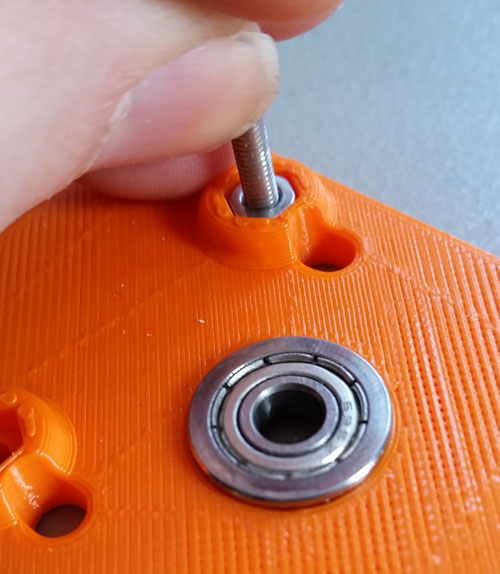
Next insert the 4 nuts by putting them on a long screw and inserting them as shown.
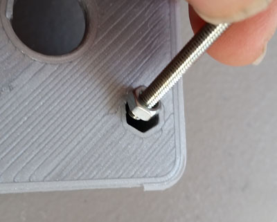
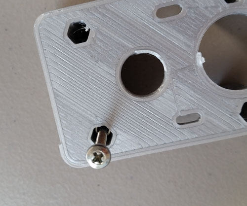
The hex holes are tilted such that they get tighter and tighter the further in you go. Leave the 4 hex nuts in the slots and remove the screw and put a shorter screw in from the other side and tighten it up until the nut gets to roughly the position shown arrowed. You want the nut to never move as you will be adding screws into these nuts much later when the base is already assembled against the printer.
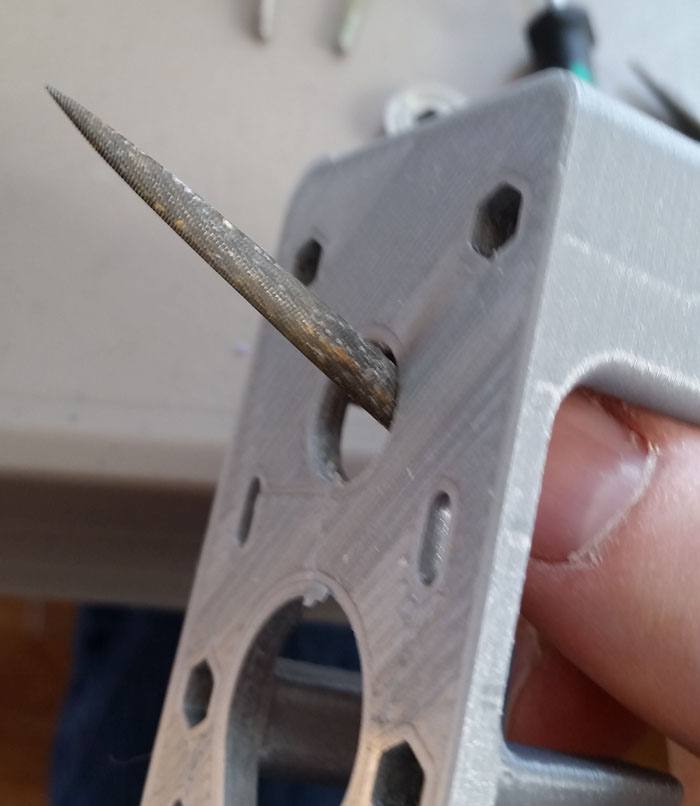
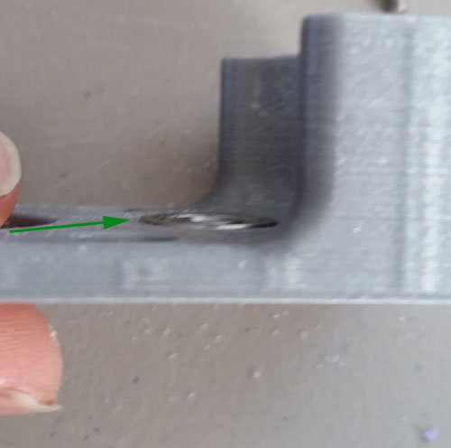
File the hole larger so that it fits a bearing.
Below - testing from the wrong side - the back side just to check for fit.
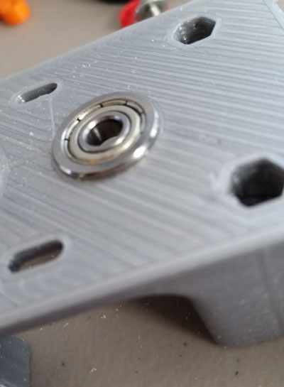
Once I had filed enough away for this to fit I turned it over and it snapped right in as shown below
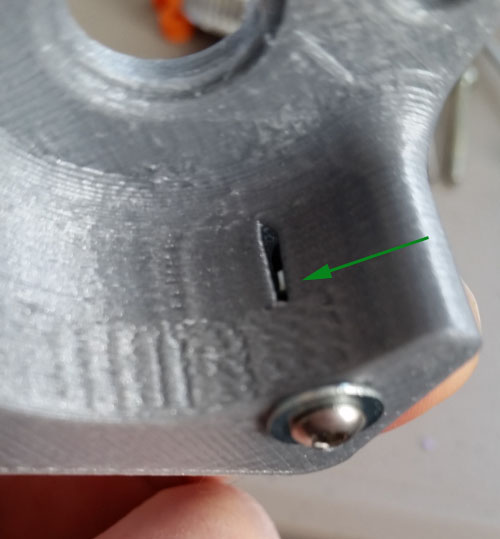
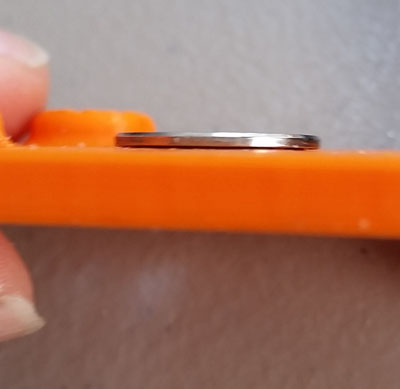
Make sure the bearing fits flush (green arrow below)
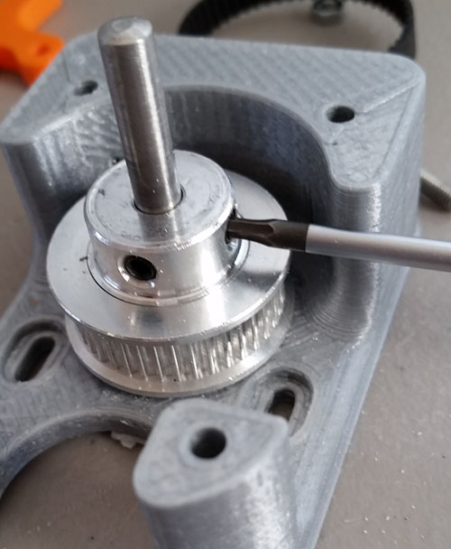
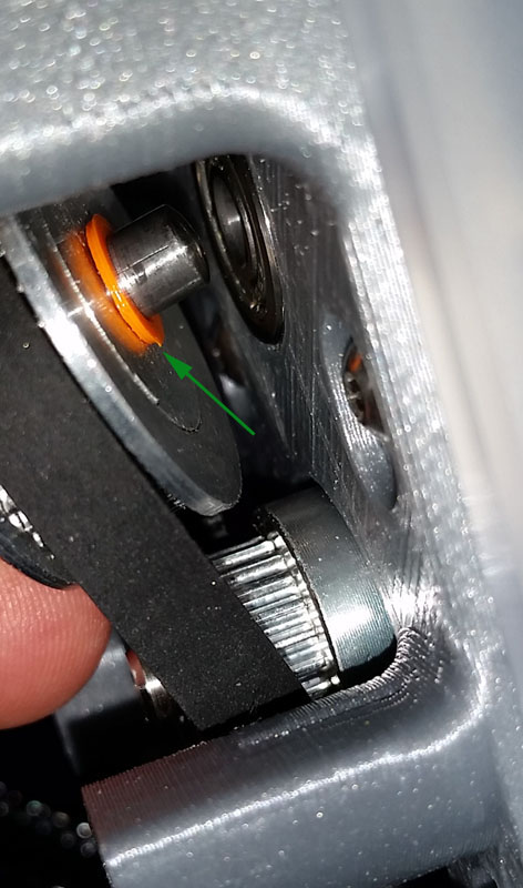
Now lets start assembling the shaft. Find the washer (orange part shown with green arrow) and put it and the 40T (40 teeth) pulley on the shaft as shown.
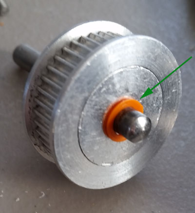
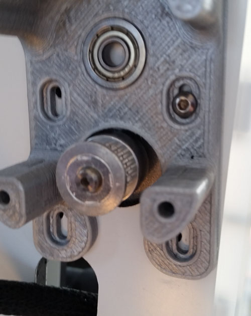
Insert this end shown into the bearing as shown (green arrow) and then put it all on a flat table pushing down gently on the shaft and tighten it very tight with a hex wrench - both set screws. Check again the view from the bottom (green arrow). Spin the pulley in place - it should spin very easily and coast.
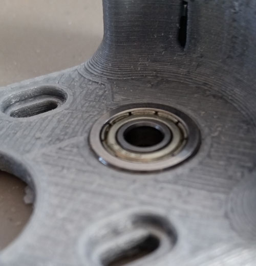
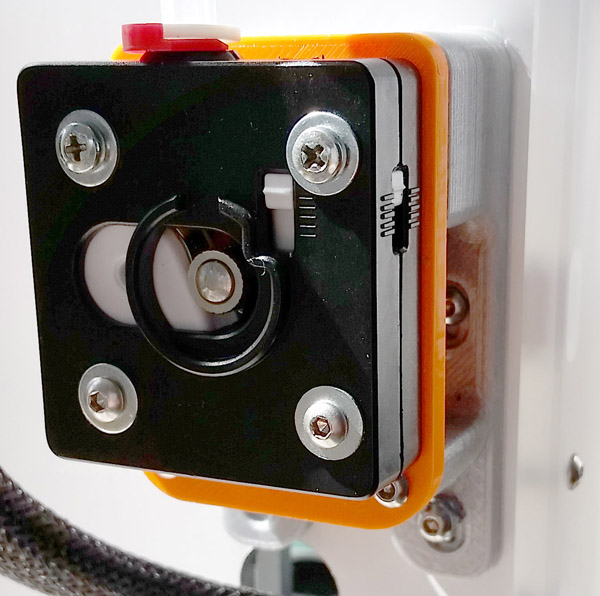
Now prepare the plate. Make sure the nuts fit (they can be very loose - it's fine) and the bearing fits as shown - it doesn't have to fit flush like it needs to with the base. If you will be using the standard UM feeder, make sure it fits nicely in the grooves for it.
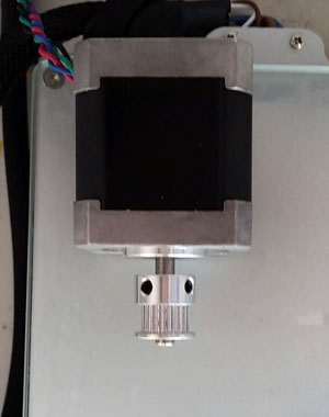
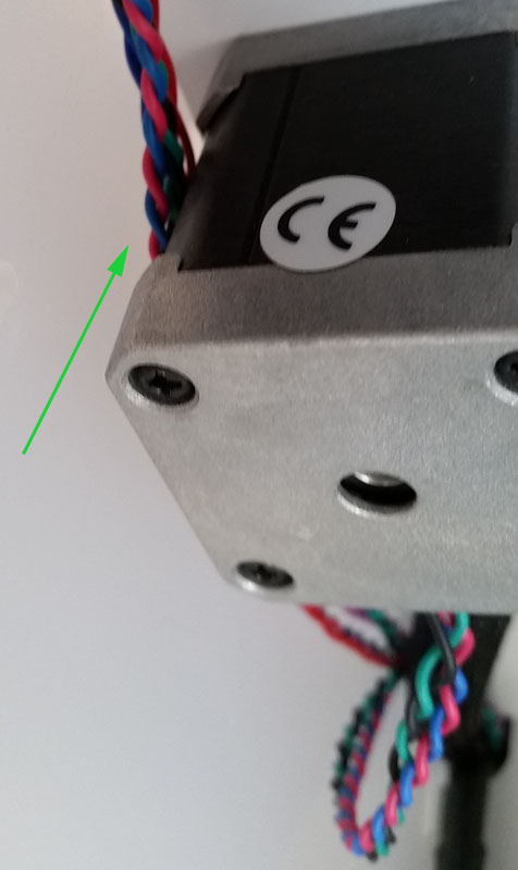
Now remove the old feeder saving the hardware - you will need the 4 washers and 2 of the 4 screws (25mm long). Have the feeder motor rest on the glass bed. Remove the old sleeve and save that. Put the 20T pulley on the motor shaft as shown. Stick the motor back through the wall and you want to tighten the pulley so there is almost no gap as shown with green arrow below. When measuring consider using a piece of thin carboard such as a business card - this is about the right distance. Also make sure the wires (green arrow) aren't in the way of the stepper when mounting it. In other words make sure the motor is flush. Tighten the 20T pulley with both set screws very very tight.
Start putting in the 4 12mm screws as shown below to hold the stepper and the base in place. Make sure again that the wires (photo above) still aren't caught under the stepper. Insert all 4 12mm screws but leave them a little loose such that the base can slide up and down in the slots.
Make sure that the orange ring (green arrow below) is on the shaft as shown - take the pulley and shaft and put the belt around it then also put the belt around the 20T pulley and secure the belt first and then start to insert the shaft into the bearing (just as shown in photo). Remember that the base (gray plastic in photo) should be able to slide up and downto reach.
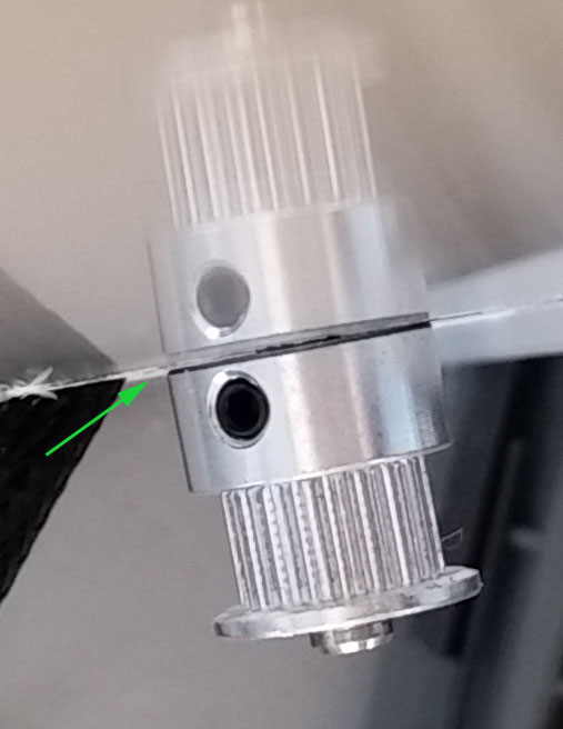
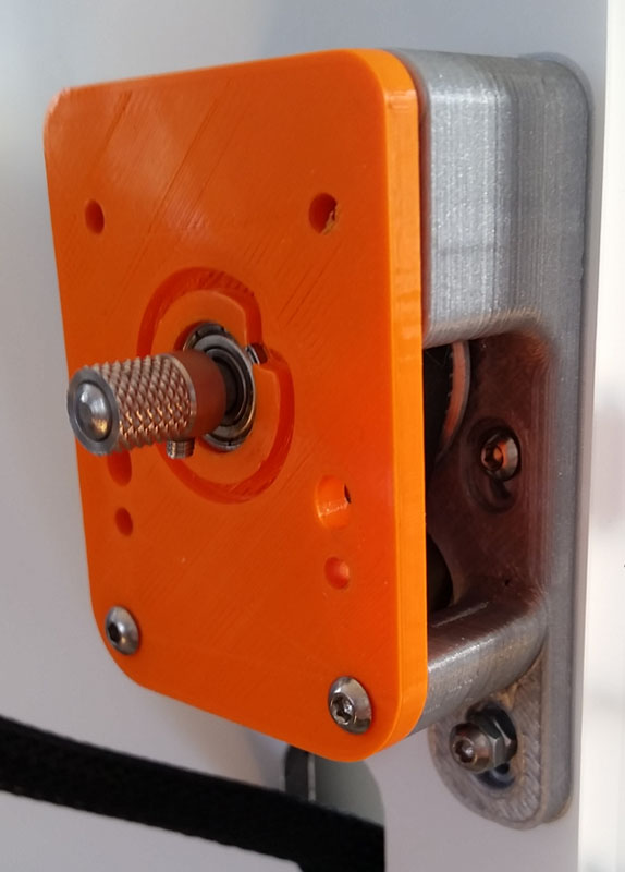
Once inserted hold it in place and put the plate over the shaft as shown below. Put the lower 2 plate screws (15mm) to hold it all together. Slide up the entire assembly to tighten the belt and tighten the 4 screws that are in slots and that hold the stepper motor. Check that the belt is tight and turn the belt with your fingers. Note that the plate will flex away from the base at the top area for now - this is expected (as shown in photo) and will be pushed against the base when we add the feeder. Put the knurled sleeve over the shaft. End should be flush with the end of the shaft as shown in photo below.
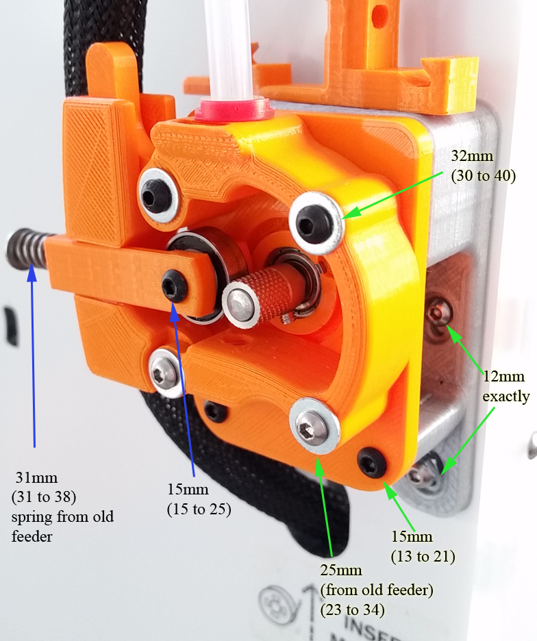
No matter if you are adding the iRoberti feeder versus the UM feeder you will want the 32mm screws for the top 2 holes and 25mm screws for the bottom 2 screws as shown in photo below. The 5 screws on the left side (no arrows) are the same lengths as their partners on the right side (green arrows). Blue arrows are related to iRoberti feeder parts.
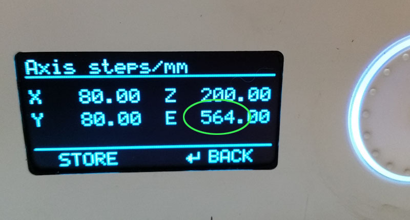
Finally - you need to set the new steps/mm setting. You want to double the old value from 282 to 564 as shown in tinker Marlin below. I don't think you can do this in regular Marlin. I strongly urge you to install tinker Marlin from here